In many areas, generally, the street light control is done manually. That means some person has to turn on the light in the evening time and turn them off in the morning time. However, there are a few drawbacks to this manual method of controlling the street light. Accidents may occur if the person forgets to turn on the street lights. Also if the street lights are not turned off in the morning then it causes electricity wastage. Also if we implement a time-based street light controlling system, then it will cause a problem since the evening start time is different in winter and summer. This project of automatic street light control can be used to overcome all these drawbacks.
₹ 3,200
Project Code: 1197

Description of the project:
The street lights are turned on at night time because the light intensity is low at night. And the street lights are turned on in the daytime since the light intensity is sufficient in the daytime.
Detailed Description of the Automatic Street Light control project:
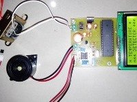
This is one of the very useful Electronics Mini Projects. LDR, microcontroller, buzzer, and relay are the main components of an automatic street light controller circuit.
- “Light-dependent resistor” sensor is used in this project. LDR is used to sense the intensity of light. The output of the LDR sensor is in the format of resistance. The resistance of LDR is inversely proportional to the light falling on the LDR. That means the resistance decreases whenever the light intensity is increased.
- We have used an 89s51 microcontroller in this project. 89s51 is an 8051 series microcontroller.
- The output of the LDR is given to the comparator circuit. This comparator has two inputs. The first input is from LDR and the second input is from the Potentiometer. This Potentiometer is used to decide the threshold level of the light intensity at which the street light should be turned on. In other words, we can say that the sensitivity of the circuit can be adjusted using this Potentiometer.
- The output of the circuit is given to the relay. Any AC or DC device can be turned on using this relay. In this project, the relay is used to turn on and off the street light.
- We have used an LCD display which displays the message if the intensity is low or high.
- A buzzer is another output device in this project. This Buzzer will be turned on whenever there is a transition in the relay. It means the buzzer will be turned on for a couple of seconds whenever the relay is turned on as well as whenever the relay is turned off.
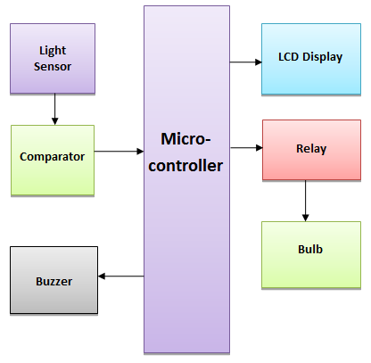
Block diagram of the project
Applications and advantages of the Automatic Street Light control project
- This project also finds applications in large societies, University campuses, industrial campuses, and many other places as Smart intelligent lights are the need of time.
- As the name suggests, the main application of this project is street light control.
- This circuit can also be modified to be used inside the house or schools and companies to control devices depending upon light intensity.