-
Ordering information
Call us or mail us for inquiries & availability: info@mtronixtech.com
-
Search projects by Price
-
Project Categories
- Robots and Robotics
- GSM based Projects
- GPS based Projects
- RFID based Projects
- Energy Saving
- Wireless Communication
- DTMF based proejcts
- SMS based projects
- RF Remote
- Mobile Controlled
- Power Saver
- Sensor based Projects
- Alcohol Sensor
- Heartbit Sensor
- Humidity Sensor
- Infrared Sensor
- Level Sensor
- Light Sensor
- LPG Gas Sensor
- Moisture Sensor
- Temperature Sensor
- Vibration Sensor
- Weight Sensor
-
Search projects by Application
Project Videos:
Landrover Robot Operated by Cellphone
Industrial Automation using Cellphone
Password based door locking
Automatic room light controller
Temperature controlled fan
Electronic voting machine
Search by Components
89c51 89s51 89s52 89v51RD2 555 ADC0808 ADC0809 AT24c16 AT24c64 AT89s52 Battery BC547 Bulb Buzzer Darlington Pair DC motor Decoder EEPROM Fan GPS GSM IR LED Keypad L239D LCD Display LDR LED LM35 LM358 Matrix keypad MAX232 Motor Driver MQ6 PC Interface Relay RFID Card RFID Reader RFID Tags Sim300 sim900 SR86 SR87 Stepper Motor SYHS220 TSOP1738
Home
Projects of 8051 Project Details
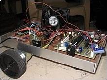
Autonomous Roving Robot for Greenhouse controlling


|
Project Cost :  8,600/-
Available in: 3 Days Project Code: 1240 
 |
Project Photographs:
 You will get a CD with this project:
CD contains following things:
1) Project Report
2) Circuit diagram
3) PCB layout
4) Microcontroller program in assembley language
5) Hex file of the microcontroller code
6) Datasheets of all the components / ICs used in the project

Description: Conventional Greenhouse controlling technique does not have concept of Robotics. This project consists of temperature, humidity & light monitoring and controlling. This unit is installed on a Robot which moves through the greenhouse on a predefined track. This project will consist of three basis modules. First is "Parameters Monitoring" second is "Parameters Controlling" and third is automatic movement of Robot on a predefined path.
A display unit will show the values of parameters like Temperature and Light. This will help for the person to know the values, for this purpose we are going to use various sensors, which will be connected to ADC.
The other module is named as parameter controlling. It can be used to control the values of temperature. We are going to use two relays for this purpose. First relay should be connected to a FAN and another should be connected to a heater. This system is useful as many times its difficult to measure and control the parameter values manually and also this module is more accurate than the domestic greenhouse system.
Robot is given a predefined motion depending upon the track of greenhouse. Robot will move throughout the greenhouse. Then it will measure the values of temperature and light while traveling through the greenhouse. At the same time it will control the values of these parameters.
PC interfacing is provided so as to send these parameter values to the PC. At the same time microcontroller will send the plant number or the position of robot to the PC.
Block Diagram:

Description in detail:
1) TEMPERATURE SENSOR:
This is first sensor which uses to sense temperature. This can be temperature sensor, say LM35. The sensor will be placed on the front panel. One can use LCD display to read the temperature.
2) LIGHT SENSOR:
This is second sensor which uses to sense light. This can be LDR. The sensor will be placed on the front panel.
3) AMPLIFIER:
Output voltage of temperature sensor is in milivolts. But the ADC requires a voltage in the range of 0 to 5volts. So we need to use an amplifier. We are going to use LM324 which is having 4 inbuilt amplifiers. Since we have two sensors, we have used this Amplifier.
4) ADC
We are going to use ADC 0808 which is 8 bit and 8 channel ADC. Since we have two inputs for ADC, we have used this ADC.
5) LCD:
Liquid Crystal Display which is commonly known as LCD is an Alphanumeric Display it means that it can display Alphabets, Numbers as well as special symbols thus LCD is a user friendly Display device which can be used for displaying various messages unlike seven segment display which can display only numbers and some of the alphabets. The only disadvantage of LCD over seven segment is that seven segment is robust display and be visualized from a longer distance as compared to LCD. Here WE have used 16 x 2 Alphanumeric Display which means on this display WE can display two lines with maximum of 16 characters in one line.
6) MOTOR DRIVER:
We need to drive the DC Motors. For this purpose we need to provide 12 volt supply to motor. Motor driver IC is used for this purpose. We are going to use L293D as a motor driver IC
7) RELAY:
We need to control the values of temperature. For this purpose we need to drive a fan and heater. We are going to use Relay for this purpose
8) PC Interfacing:
We are going to use MAX 232 for the purpose of PC interfacing, using this module, we can send various data like temperature, light to the PC.
9) MICRO-CONTROLLER (8051):
This is the most important segment of the project, i.e. the microcontroller 8052. The controller is responsible for detection and polling of the peripherals status. It is responsible for making. It is responsible for prioritizing all the devices attached to it.
WE have used the ATMEL 89s51 microcontroller. The AT89S51 is a low-power, high-performance CMOS 4-bit microcontroller with 8K bytes of in-system programmable Flash memory. It has got 32 I/O lines, Watchdog timer, two data pointers, two 16-bit timer/counters, six-vector two-level interrupt architecture, a full duplex serial port, on-chip oscillator, and a clock circuitry.
APPLICATIONS:
This electronic circuit can be used for the following application
1) To calculate and control the temperature and light of the environment in the greenhouse.
2) Same unit can be used in the industry to control the temperature and light of various units in the industry.
Tags: Agricultural project
Question and answers about this project:
Question: What is the size of Greenhouse Robot?
Answer: Size is approximately 15 inch by 10 inch, actual size may vary.
Do you have question or any feedback about this project?
Please email your questions to: info @ mtronixtech.com